
▣ Classification of Piping System Stresses
-
Primary Stress
-
Stress induced by forces and moments applied internally and externally to the piping system, including bending stress from internal pressure, self-weight, wind, and other factors, as well as torsional stress.
-
The safety of primary stress is evaluated by comparing it with the allowable stress of the piping material.
-
-
Secondary Stress
-
Stress caused by thermal expansion due to the temperature of the fluid flowing through the pipeline. Even if this stress exceeds the yield strength of the material, it can enter a safe stress range due to stress relaxation.
-
Unlike primary stress, secondary stress is not compared directly with the allowable stress but rather with the allowable stress range to determine safety.
-
-
Allowable Stress
-
The stress level that a material can safely withstand under various temperature conditions concerning primary stress.
-
These values are provided in the ANSI Code.
-
.
.
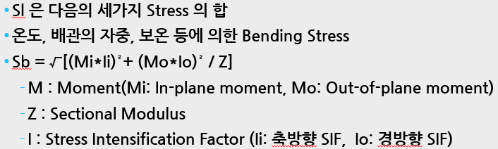
▣ Types of Stresses
-
SI: Longitudinal Stress
-
Sc: Circumferential Stress
-
Sr: Radial Stress
-
Ss: Shear or Torsional Stress
.
▣ Static Stress Analysis
-
Sustained Load: Includes dead weight and internal pressure.
-
Occasional Load: Includes wind load and seismic load.
-
Support: Analysis of self-weight, hydrodynamic pressure, and reaction forces.
-
Evaluation of Impact on Connected Equipment Due to Forces & Moments:
-
Includes rotating machinery such as pumps, compressors, turbines, and air fin coolers.
-
Evaluates nozzle load stress for vessel nozzles (cylindrical, spherical) and heaters.
-
-
Stiffness Ring Design for Vacuum Lines.
-
Underground Stress Analysis: Includes thermal and earth pressure design.
-
Branch Reinforced Pad Design.
.
▣ Dynamic Stress Analysis
-
Safety Valve Thrust Calculation.
-
Vibration: Includes considerations for reciprocating compressors and two-phase flow.
-
Seismic Analysis: Includes static method and response spectrum method.
-
Surge Analysis: Involves determining energy absorption devices due to sudden pressure rises in long-distance high-speed fluid pipelines, caused by rapid valve switching or power outages.
.
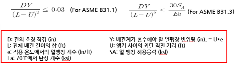
▣ Flexibility Analysis of Piping
-
Flexibility analysis involves reviewing whether the piping between fixed points has adequate flexibility to accommodate thermal expansion, ensuring that pipe supports are designed to withstand sustained and occasional loads.
-
The flexibility analysis is performed to ensure the proper layout of the piping, and it typically does not require a special calculation procedure or the creation of a calculation report as part of the piping stress analysis documentation.
-
It is not necessary to perform flexibility analysis for every piping system.
Cases Where Analysis is Not Required (ASME B31.1):
-
The installed piping system is identical to a system with proven usage or is a replacement for such a system.
-
The installed piping system is judged to be adequate when compared to a previously stress-analyzed system.
-
The installed piping system has a constant diameter, no restraints between two anchors, and the total number of operating cycles is 7,000 or less, satisfying specific equations.
.
▣ Piping Stress Analysis Codes
-
API675: Positive Displacement Pumps Controlled Volume
-
API-618: Reciprocating Compressors For General Refinery Services
-
NEMA SM23: Steam Turbine For Mechanical Drive Service
-
API-560: Fired Heaters For General Refinery Services
-
API-610: Centrifugal Pumps For General Refinery Service
-
API-611: General-Purpose Steam Turbines For Refinery Service
-
API-612: Special-Purpose Steam Turbine For Refinery Service
-
API-617: Centrifugal Compressors For General Refinery Service
-
API-661: Air-Cooled Heat Exchangers For General Refinery Service
-
API-650: Welded Steel Tanks for Oil Storage
-
API-1102: Liquid Petroleum Pipelines Crossing Railroads and Highways
-
ANSI A58.1: Minimum Design Loads For Buildings and Other Structures
-
ANSI B31.3: Chemical Plant and Petroleum Refinery Piping
.
▣ Stress Analysis Report
-
After performing stress analysis, document the results and retain them for reference.
-
Includes applied codes, computer programs, and general information.
-
Assumptions applied in the design.
-
Hold Item Lists.
-
Isometric Drawings used for piping stress analysis (including input data).
-
Computer input data (design conditions, material properties).
-
Basis for thermal expansion displacement calculations for equipment.
-
Review of nozzle loads based on load combinations.
-
Load Summary Sheets for anchors and supports based on load combinations.
-
Computer-generated results, etc.
-
.
▣ Review Items After Analysis of Self-Weight, Occasional Load, and Thermal Expansion
-
Is the sag of the piping due to self-weight within acceptable limits?
-
Are the loads on equipment nozzles within allowable limits?
-
Is the maximum stress within the allowable stress?
-
Are excessive loads generated on the designed anchors?
-
Is there an upward load (Up-Lift Load) due to the load?
-
Does the thermal expansion displacement cause interference with nearby piping?
-
Are there lower points than the drain point due to thermal expansion?
-
Are the analysis results within allowable limits for each operating mode?
.
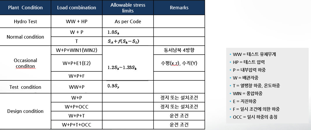
▣ Load Combinations and Allowable Stress
-
Design Condition:
-
Considerations include the piping’s self-weight (including the weight of the fluid, insulation, concentrated loads such as valves), design pressure, seismic load, etc.
-
-
Normal Operating Condition During System Operation:
-
Includes piping self-weight, internal pressure, thermal expansion load, and abnormal conditions that may occur during operation.
-
Includes dynamic loads, internal pressure, and thermal expansion loads.
-
-
Test Condition:
-
Testing considerations.
-
.
▣ Load Combinations (ASME B31.1)
.
▣ Coordination with Other Disciplines
DisciplineMain Coordination Tasks
No. |
Description |
Structural |
– Transfer of dead load and anchor load, thermal load transmission– Verification of seismic and wind load design criteria |
Civil |
– Transfer of foundation load for independent supports– Receipt of seismic and wind load design criteria |
Equipment |
– Transfer of nozzle load (Force & Moment) results– For general vessel nozzles, verification of analysis results by equipment design personnel– For high-temperature, high-pressure vessels, verification by equipment design personnel or manufacturer |
Mechanical |
– Request for verification of rotating equipment nozzle loads– Confirmation of nozzle integrity by mechanical personnel or manufacturer |