
▣ Overview
- Design Conditions and Criteria
- Components for Pressure Design of Piping Components
- Limitations of Piping Components
- Limitations of Piping Joints
- Expansion, Flexibility, and Support
- System Descriptions
▣ Scope and Definitions
- The standards and specifications included for reference are shown in Table 126.1. The referenced editions are included in the annual Addenda revisions.
- The term “piping” used in this code includes the pressure-retaining components such as pipe, flanges, bolting, gaskets, valves, relief devices, fittings, and other piping components manufactured in accordance with the standards listed in Table 126.1 or specially designed.
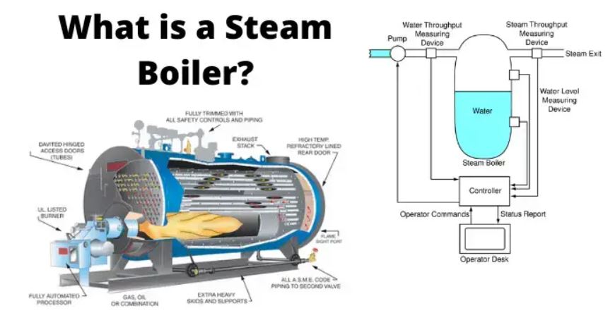
- Requirements for boiler installations must comply with ASME Sec.I and the Pressure Vessel Code, PG-60.
- All legal requirements specified in section 136.1 do not relieve the customer of the inspection obligations.
- This code covers the external piping for power boilers and high-temperature, high-pressure water-tube boilers, which generate steam at pressures exceeding 15 psig [1103 kPa(gage)], or produce hot water at pressures exceeding 160 psig [1103 kPa(gage)] and/or temperatures exceeding 250℉ (120℃).
- Piping between terminal points and valves or the valves required by section 122.1(B) must comply with the Data Report, inspection, and stamping requirements as mandated by ASME Sec.I.
- The quality control system must meet the requirements of the ASME Boiler and Pressure Vessel Code, Section I.
- Welding terminology used in this code follows the definitions in AWS A3.0.
·
▣ Design Part I
- The internal design pressure must not be less than the maximum sustained operating pressure (MSOP) of the piping system, including the effect of static head.
- Piping subject to external pressure must be designed for the maximum differential pressure expected during operation, shutdown, or test conditions.
- Unless justified by calculations or tests, the fluid temperature should be assumed as the metal temperature. The design temperature must not be less than the average of the fluid temperature and the external wall temperature.
- When the fluid passes through heat exchangers in series, the design temperature of each part of the system must match the highest temperature conditions that can be generated by the heat exchanger in that part of the system.
- The design temperature for piping carrying steam, boiler feedwater, and high-temperature water from combustors like boilers, reheaters, superheaters, and economizers must be based on the maximum temperature guaranteed by the equipment manufacturer for expected continuous operating conditions.
- One form of internal shock load is caused by the propagation of pressure waves resulting from a sudden change in fluid momentum, known as water or steam ‘hammer’.
- Exposed piping must be designed to withstand wind loads determined from meteorological data.
- In regions with snow or ice loading conditions, these loads must be locally substituted and considered in the design.
- The materials of bellows-type, slip joints, sleeves, balls, or swivel joints and flexible metal hose assemblies must comply with this Code. These products must not be used in any piping system connecting the boiler and the first stop valve.
- The criteria for determining allowable stress values within this Code section are the same as those in ASME BPVC Section II, Part D, Appendix 1
·
▣ Design Part II
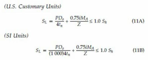
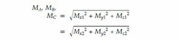
- ASME B 31.1 Para. 104.8.1 : The equation representing stress due to sustained loads is crucial.
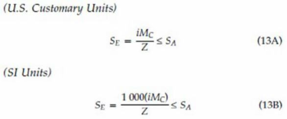
- ASME B 31.1 Para. 104.8.3 :Stress range due to thermal expansion must be considered.
- Stress Concentration Factors: Need to be evaluated in the design process.
This content provides an overview and detailed guidance on the power piping code requirements, focusing on design conditions, component limitations, and compliance standards as per ASME guidelines.